Search This Blog

Friday 11 November 2011

Brushless DC Motors

Introduction:
Conventional dc motors are highly efficient and their characteristics make them suitable for use as servomotors. However, their only drawback is that they need a commutator and brushes which are subject to wear and require maintenance. When the functions of commutator and brushes were implemented by solid-state switches, maintenance-free motors were realised. These motors are now known as brushless dc motors.

Basic structures:
The construction of modern brushless motors is very similar to the ac motor, known as the permanent magnet synchronous motor. Fig.1 illustrates the structure of a typical three-phase brushless dc motor. The stator windings are similar to those in a polyphase ac motor, and the rotor is composed of one or more permanent magnets. Brushless dc motors are different from ac synchronous motors in that the former incorporates some means to detect the rotor position (or magnetic poles) to produce signals to control the electronic switches as shown in Fig.2. The most common position/pole sensor is the Hall element, but some motors use optical sensors.


Fig.1 Disassembled view of a brushless dc motor

Although the most orthodox and efficient motors are three-phase, two-phase brushless dc motors are also very commonly used for the simple construction and drive circuits. Fig.3 shows the cross section of a two-phase motor having auxiliary salient poles.


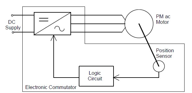
Fig.2 Brushless dc motor = Permanent magnet ac motor + Electronic commutator

Comparison of conventional and brushless dc motors:
Although it is said that brushless dc motors and conventional dc motors are similar in their static characteristics, they actually have remarkable differences in some aspects. When we compare both motors in terms of present-day technology, a discussion of their differences rather than their similarities can be more helpful in understanding their proper
applications. Table 1 compares the advantages and disadvantages of these two types of motors. When we discuss the functions of electrical motors, we should not forget the significance of windings and commutation.

Fig.3 Two-phase motor having auxiliary salient poles

Commutation refers to the process which converts the input direct current to alternating current and properly distributes it to each winding in the armature. In a conventional dc motor, commutation is undertaken by brushes and commutator; in contrast, in a brushless dc motor it is done by using semiconductor devices such as transistors.


For more detail click on the following link:

Thursday 10 November 2011

Electrical Engineering Lab Viva Questions :

Experiment of DC Machine:
1. What are the difference between electrical motor and generator?
2. What is the need for starters?
3. Which is the basic protective device in any circuit?
4. How to find out the fuse rating?
5. Name the different types of DC starters?
6. What is the role of Holding Coil in a DC starter?
7. Why is the armature rheostat of dc motor kept at maximum resistance position?
8. Write the e.m.f. equation of DC machine.
9. Write the torque equation of DC motor.
10. Name the parts of dc machine.
11. What is the use of commutator and brushes?
12. Draw the electrical characteristics and N/Ia characteristics of a DC shunt motor.
13. How are the ammeters and voltmeters connected in any circuit?
14. What are the methods of speed control of dc motors?
15. What is back emf? Give its significance.
16. What is the difference between self excited and separately excited machines?
17. Name the types of self excited dc machine.
18. What are the losses in dc machine?
19. How is the eddy current loss minimized in dc machine?
20. Why is armature resistance less than field resistance of dc shunt machine?
21. Why is armature resistance more than field resistance of dc series machine?
22. Why shouldn’t dc series motor started at no load?
23. What is L, F, A, N in dc starters?
24. Given 4 terminals without indication. How will you manage to find the field and
armature terminals of i) dc shunt machine ii) dc series machine.

Experiment of AC Machine:
1. What is the principle of a transformer?
2. What are the types of transformer?
3. What are the applications of transformer?
4. Why is the capacity of a transformer specified as KVA and not as KW?
5. What is the condition for maximum efficiency of a transformer?
6. Why is the efficiency of a transformer higher than that of motors?
7. What is the purpose of OC and SC tests?
8 .Why is the core of a transformer laminated?
9. What is meant by regulation?
10. Define the term transformation ratio?
11. What are the components of no load current?
12. How are the parameters referred to the HV or LV side? Explain with an example.
13. What is meant by power factor? Explain.
14. What will happen if dc supply is connected to transformer?’
15. What are the parts of transformer?
16. Why are synchronous motors not self starting? What are the methods of starting?
17. Why are single phase induction motors not self starting? Classify them according to the starting methods.
18. Why is synchronous motor referred as doubly excited machine?
19. What is slip of an induction motor?
20. Why is always the induction motor running with less than the speed of rotating
magnetic field?
21. What are the types of 3 phase induction motors?
22. Why is 3 phase induction motor referred as rotating transformer with short-circuited secondary?
23. What is the use of end rings in squirrel cage induction motor?
24. What is mutual inductance?
25. What is the principle of motor, generator and transformer?
26. How will you reverse the direction of rotation of i) dc motor ii) ac motor?
27. What is M, L, C, and V in wattmeter?
28. What is E and C in autotransformer?
29. What are the disadvantages of low power factor?
30. What are the methods of speed control of ac motors?
31. Given transformers A and B with following details:
A: η= 96% & reg: 5.8%
B: η= 94% & reg: 5.2%
Which transformer will you select? Justify your answer.
32. What do you mean by hunting?
33. What is meant by magnetizing current and active (working) component of current
with respect to transformer?
34. Give the relation between line and phase values of
i) star connected network
ii) delta connected network.
35. When can the squirrel cage machine be loaded to its fullest capacity? i) Star
connection of stator ii) delta connection of stator.
36. How can the eddy current and hysteresis loss of any machine be minimized?
37. What are the methods of electrical braking?
38. Draw the torque-slip characteristics of 3 phase induction motor and explain.
39. State the Farraday's Law of Electromagnetic Induction?
40. Explain the right hand thumb rule.
41. Draw the open and short-circuit characteristics of an alternator.

Sunday 9 October 2011

Basic of Electrical Energy

FUEL CELLS- The Next Generation Of Electrical Power


FUEL CELLS- An Introduction


Whereas the 19th Century was the century of the steam engine and the 20th Century was the century of the internal combustion engine, it is likely that the 21st Century will be the century of the fuel cell. Full cells are now on the verge of being introduced commercially,revolutionizing the way we presently produce power. Fuel cells can use hydrogen as a fuel, offering the prospect of supplying the world with clean, sustainable electrical power. Hydrocarbons such as natural gas and alcohols like methanol are sometimes used. Fuel cells are different from batteries in that they require a constant source of fuel and oxygen to run, but they can produce electricity continually for as long as these inputs are supplied.

Welsh Physicist William Grove developed the first crude fuel cells in 1839. The first commercial use of fuel cells was in NASA space programs to generate power for probes, satellites and space capsules.

WHAT IS FUEL CELL?

Fuel cells are electrochemical devices that convert the chemical energy of a reaction directly into electrical energy.  The basic physical structure or building block of a fuel cell consists of an electrolyte layer in contact with a porous anode and cathode on either side. They convert hydrogen, or hydrogen-containing fuels, directly into electrical energy plus heat through the electrochemical reaction of hydrogen and oxygen into water. The reaction of this process is as follows: 
Anode Reaction: CO3-2 + H2 → H2O + CO2 + 2e-
Cathode Reaction: CO2 + ½O2 + 2e- → CO3-2
Overall Cell Reaction: H2 + ½O2 → H2O


Because hydrogen and oxygen gases are electrochemically converted into water, fuel cells have many advantages over heat engines. These include: high efficiency, virtually silent operation and, if hydrogen is the fuel, there are no pollutant emissions.  If the hydrogen is produced from renewable energy sources, then the electrical power produced can be truly sustainable.


The basic diagram of a Hydrogen fuel cell is shown in fig.1.1

Fig.1 Basic Diagram of a Hydrogen fuel cell

FUEL CELL APPLICATIONS

As a result of the inherent size flexibility of fuel cells, the technology may be used in applications with a broad range of power needs.  This is a unique feature of fuel cells and their potential application ranges from systems of a few watts to megawatts.
Fuel cell applications may be classified as being either mobile or stationary applications.  The mobile applications primarily include transportation systems and portable electronic equipment while stationary applications primarily include combined heat and power systems for both residential and commercial needs.
  1. Transportation

Cars
All the world leading car manufacturers have designed at least one prototype vehicle using fuel cells.  Some of the car manufacturers (Toyota, Ford) have chosen to feed the fuel cell with methanol, while others have preferred to use pure hydrogen (Opel has used liquid hydrogen, General Motors has stored hydrogen in hydride form).  In the short term there is a general trend for the car manufacturers to use reformed methanol as the fuel type for the fuel cell.  However, over in the long term hydrogen remains the fuel of choice for the majority of the car manufacturers.

NECAR Program

The NECAR program, initiated in 1994, was designed in 4 phases leading to 4 prototypes of electric vehicles.  The aim of this program was to show the feasibility of such a vehicle and then to improve the technology during each of the design phases.

      Buses
In 1993, Ballard Power Systems demonstrated a 10 m light-duty transit bus with a 120 kW fuel cell system, followed by a 200 kW, 12 meter heavy-duty transit bus in 1995.  These buses use no traction batteries and operate on compressed hydrogen as    the on-board fuel. 
In 1997, Ballard provided 205 kW PEMFC units for a small fleet of hydrogen fuelled, full-size transit buses for demonstrations in Chicago, Illinois, and Vancouver, British Columbia. The marketing phase is envisaged for 2002.

  1. Portable Electronic Equipment 
In addition to large-scale power production, miniature fuel cells could replace batteries that power consumer electronic products such as cellular telephones, portable computers, and video cameras.  Small fuel cells could be used to power telecommunications satellites, replacing or augmenting solar panels.  Micro-machined fuel cells could provide power to computer chips.

3.  Combined Heat and Power Systems
The primary stationary application of fuel cell technology is for the combined generation of electricity and heat, for buildings, industrial facilities or stand-by generators. Because the efficiency of fuel cell power systems is nearly unaffected by size, the initial stationary plant development has focused on the smaller, several hundred kW to low MW capacity plants.  “The plants are fuelled primarily with natural gas, and operation of complete, self-contained, stationary plants has been demonstrated using PEMFC, AFC, PAFC, MCFC, SOFC technology”.

Wednesday 5 October 2011

Faraday's Law of Electromagnetic Induction


Faraday's Law of Electromagnetic Induction

Electromagnetic Induction:

The phenomenon by which an emf is induced in a conductor when it is cut by magnetic flux is known as electro-magnetic induction.

Faraday’s First Law


It states that, When-ever a conductor cuts a magnetic field or vice-versa, an e.m.f. (electro-magnetic force) is induced in it and it sets up in such a direction so as to oppose the cause of it.


Faraday’s second law


It states that the magnitude of induced e.m.f. is equal to the rate of change of flux linkage.
Mathematically
e = -N dØ / dt
where   e= Induced emf
            N= Number of turns of coil
           dØ / dt = Rate of change of flux
the minus sign represents that the induced emf or current sets up in a direction so as to oppose the cause of it ( according to Lenz’s Law).


Lenz’s Law

Lenz’s law states that:
   "The direction of induced current is always such as to oppose the cause which produces it".
   That is why a –ive sign is used in Faraday’s law.